
There is a particular quietness to a working drawing. A working drawing directs making, fitting, inspection or alteration; every line and note serves that task.
That is what I find compelling about these three sheets. They are not illustrations of machines; they are part of the work that brought machines into being. The 1940 Brush-Koela gas-producer drawing, the circular milling-machine plan and the Coventry Ordnance Works gun-lathe drawing all have the visual authority of blueprints, but their real subject is decision-making: which section is cut through, where a line is hidden, what needs a dimension, and what can be left to the knowledge of the person reading it.
My partner is an engineer, and he looks at them rather differently from me. I am held first by the paper, the folds and the lettering. He begins with the views: what is being shown, where the cut is taken, and what the draughtsman is trying to explain to the workshop. Conversations like that make the drawings feel less forbidding. I still do not pretend to read every line, but I have begun to understand that the difficulty is part of their honesty. A good drawing does not merely show an object; it makes clear what must be understood before the object can be made.
The drawing as an instruction to look
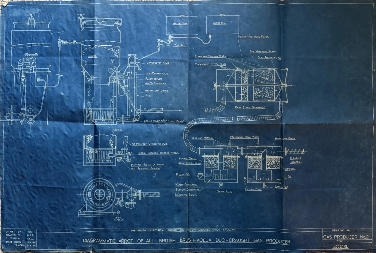
The first sheet is a 1940 Brush-Koela duo-draught gas-producer blueprint, issued by The Brush Electrical Engineering Co. Ltd of Loughborough. Across its lower edge, the title block calls it a “diagrammatic arrangement” of the gas producer. That phrase is worth noticing. It is not an exhaustive account of every nut and fitting; it is a drawing arranged to explain how the system is meant to work as a whole.
The title block is the natural place to begin with any old technical drawing. It holds the company name, drawing number, type and date, while the wider sheet spreads the machine out into readable parts. Here, tanks, hopper, valves, flash boiler, filters and pipework are given names. Arrows point through the system. Cut sections open the parts which would otherwise remain enclosed. The result is almost architectural: one can follow the route from the water tanks to the producer, from the producer through the scrubber and towards the line marked “to engine induction”.
My partner’s explanation was simple enough to stay with me: do not try to read a drawing all at once. First ask what is in front of you. Then ask what has been sliced through so that the inside can be seen. Only after that should you follow the connections. In this sheet, that advice changes the experience completely. What first appears to be a crowded field of pale lines becomes a deliberate sequence: fuel and water, heat and air, cleaning and delivery.
“Diagrammatic arrangement” is an admission of purpose. The sheet is not the machine itself; it is a way of bringing the right parts of the machine into view.
The date—8 April 1940—makes the sheet difficult to regard as merely decorative. Yet it would be wrong to add a wartime story that the drawing does not itself tell. It is enough to say that it belongs to a moment when mechanical reliability and technical knowledge had an unusual urgency. That proximity has a private resonance for me. We only learned in 2016, long after my grandfather had died, that he had worked at Bletchley Park during the war as a Bombe technician. These drawings are not his, and I do not make a connection I cannot prove. But they make it easier to imagine a world in which careful technical work was both exacting and largely unseen.
A photograph placed back on the plan
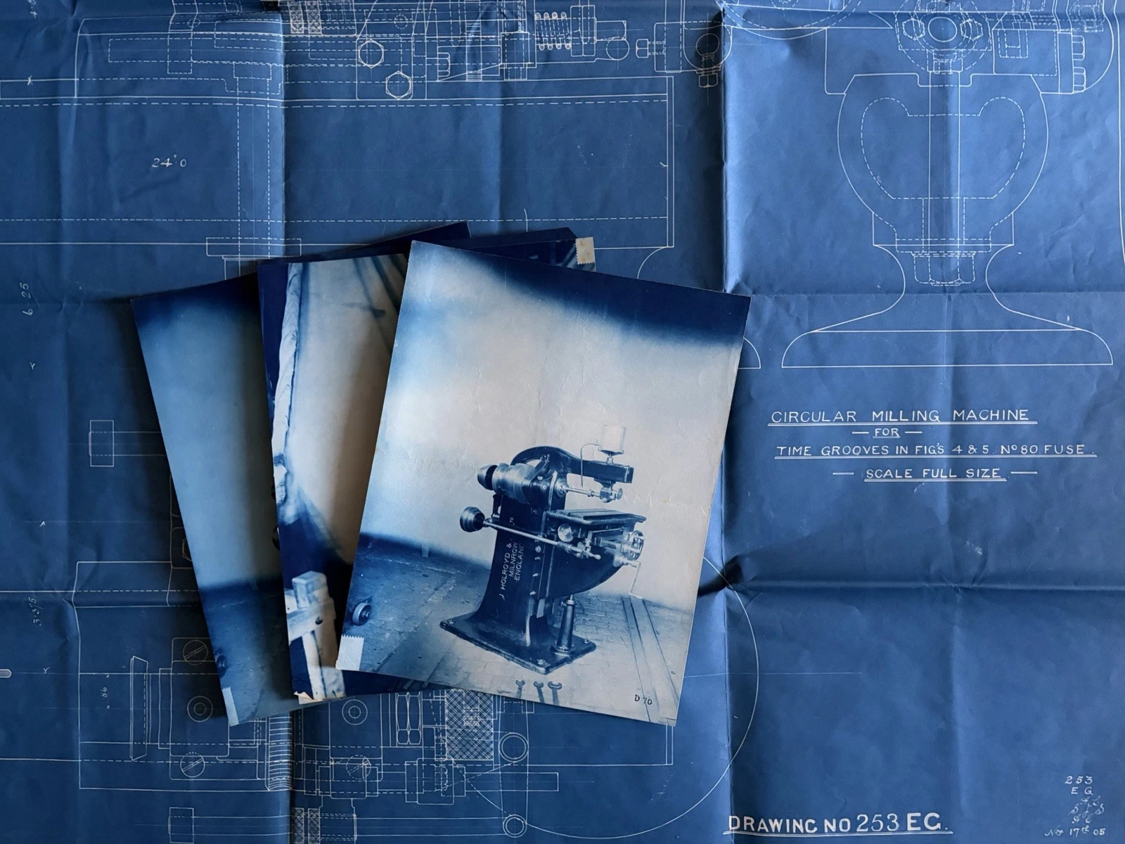
The circular milling-machine blueprint feels different from the first sheet because the photographs are still laid across it. The machine appears not only as lines but also as an object: a compact piece of equipment standing in a workshop, with its cast body, controls and working surface made visible in the photographs. The drawing behind it gives the machine its measured outline; the photographs return weight, scale and texture.
At the right, the title names a “Circular Milling Machine” and records that it was intended for “time grooves in figs 4 & 5 No. 80 fuse”. The inscription is precise, but it is also a reminder of the limits of a first reading. It identifies a particular operation and a particular drawing number; it does not, by itself, tell the whole story of the machine, its date or its working life. I prefer to leave that uncertainty visible rather than turn an intriguing phrase into a larger claim.
What my partner immediately noticed were the different kinds of line. The heavy outside line establishes the visible shape. Finer broken lines suggest elements concealed within or behind a surface. The view at the right is not a second decorative image; it turns the object so that a different relationship can be measured. This is one of the pleasures of an engineering drawing once somebody has pointed it out: a view is an argument. It says, in effect, that this is the angle from which a certain problem can be solved.
The title block keeps the record honest
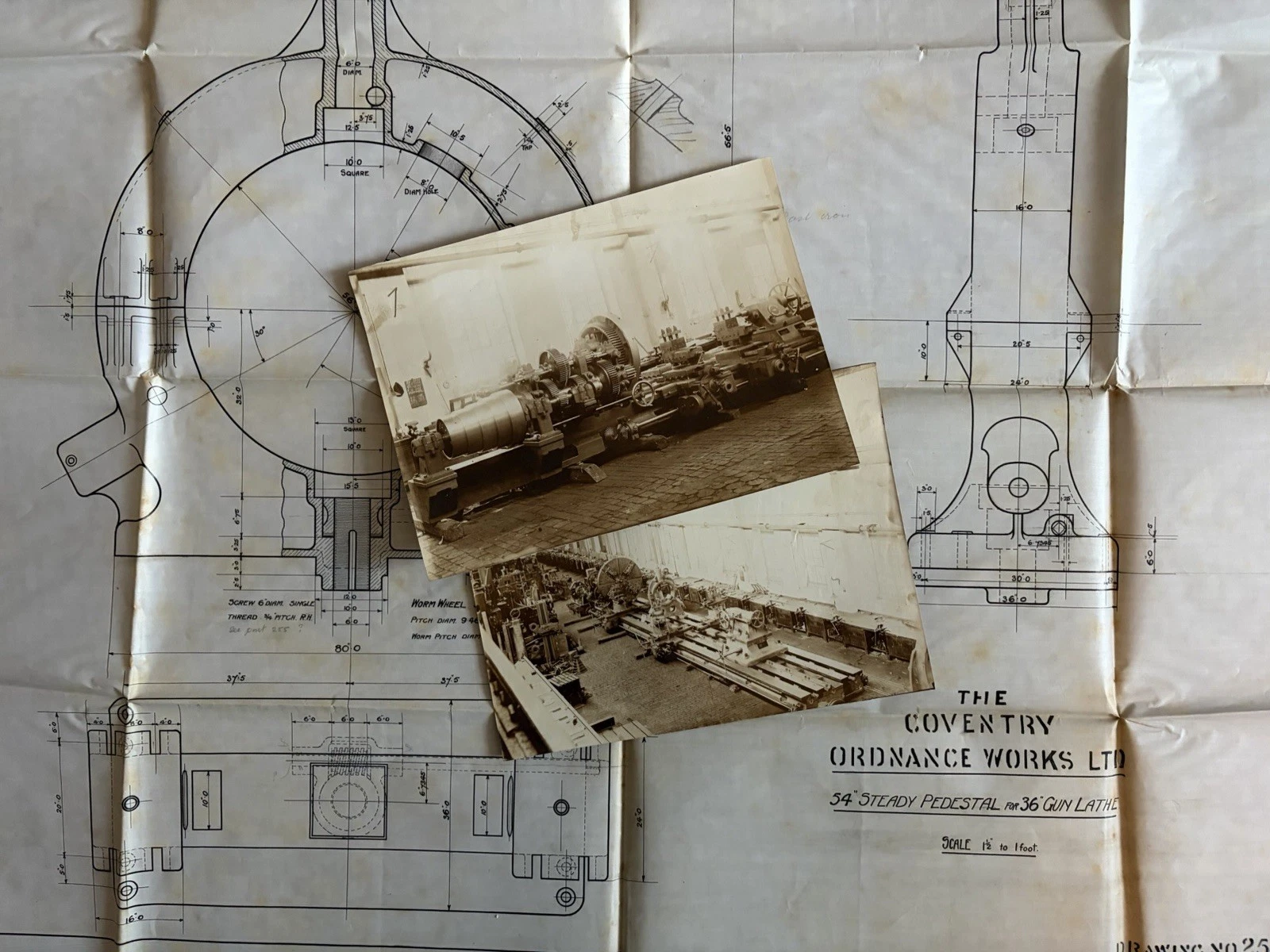
The third drawing, a 1906 Coventry Ordnance Works gun-lathe blueprint, makes the title block especially rewarding. Here it gives the maker—The Coventry Ordnance Works Ltd—the component, a “54 inch steady pedestal for 36 inch gun lathe”, and the scale: half an inch to one foot. Those few lines pull the eye back from the impressive sweep of the drawing and towards its practical purpose. This is not a portrait of a whole lathe. It is a working record for one supporting part of one much larger machine.
At first glance the cross-section at the left can look abstract: a curve, a central void, an accumulation of measurements. Beside it, the elevation establishes height and fixing points; below, the plan shows the footprint. Once those three views are read together, the sheet begins to tell a more intelligible story. The same part has been turned, opened and flattened so that the workshop can see what a single view could never provide.
The two original photographs are an unexpected gift because they keep the drawing from floating free of its object. They show the long lathe and its scale within the workshop, while the blueprint isolates the pedestal and gives it a name, dimensions and a place in the larger arrangement. I find that movement between photograph and line deeply satisfying. The photograph says: this existed. The drawing says: this is how one part of it had to be understood.
What remains on the sheet
These drawings have made me think more carefully about the word “blueprint”. It is often used loosely for any early plan, as if a technical drawing were simply an idea before the real thing. But the paper is not preliminary in that simple sense. It is a working surface: a place where an object has already been considered from more than one direction, and where a future action can be checked against a shared set of lines.
That is why the folds, creases and softened edges matter. They do not prove a particular workshop history, but they prevent the sheets from becoming too pristine in the mind. These were large papers intended to be opened, consulted and folded again. The stains and wear sit beside careful lettering and exact measurements. They make the drawings feel human without making them less precise.
I return to them partly because they join my present to a past I can only approach in fragments. My grandfather’s war work remains mostly unknown to us; my partner’s professional eye makes these other technical papers newly legible. Between them is a modest lesson in attention. I cannot recover every process or read every symbol. I can, however, stand over a large sheet of paper and see how much patient thought has been placed there for somebody else to use.
Collector's note
When looking at an old engineering drawing, I begin with the title block: maker, drawing number, component, date and scale. Then I compare the views—plan, elevation and section—and look for the small evidence that tells us how the sheet has survived: folds, tracing marks, annotations, stamps and accompanying photographs. The essential question is not whether every line can be translated immediately, but whether the drawing still preserves the relationship between object, maker and purpose.
Bibliographical note
This note considers three original drawings: the 1940 Brush-Koela duo-draught gas producer, the circular milling machine, and the 1906 Coventry Ordnance Works gun-lathe pedestal. The interpretations above distinguish between visible information on the sheets and context supplied by the accompanying photographs.
For the wider archival context of engineering plans and measured drawings, see Historic England’s guide to plans, drawings and documents. The personal reference to Bletchley Park is included as family history, not as evidence about these particular objects.